|
 |
|
|
|
|
|
 |
|
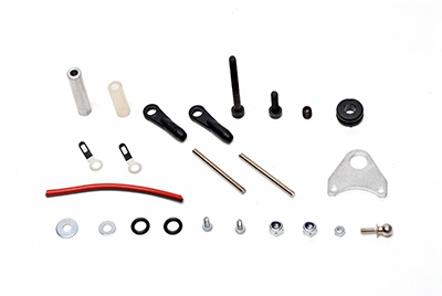
Don't forget the
silicone tube. |
|
| |
|
|
 |
|
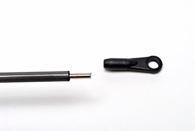
Epoxy one side first.
Do not epoxy the other end until you mount the tail
boom. |
|
| |
|
|
 |
|
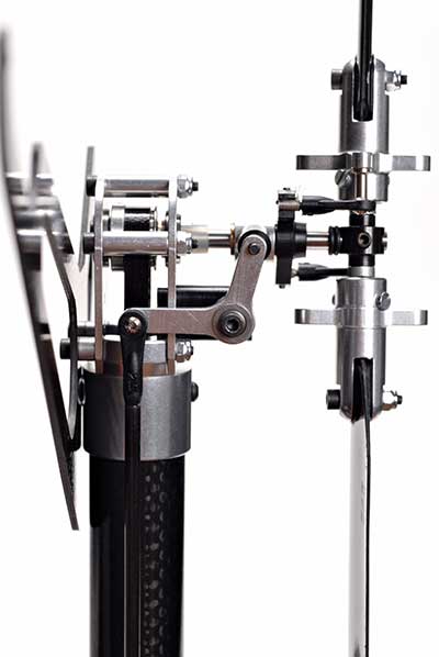
Check for smooth
movement of the assembly. Resize the ball joints
as necessary. |
|
| |
|
|
 |
|
| |
|
|
 |
|
| |
|
|
 |
|
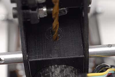
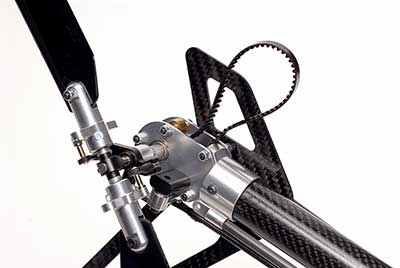
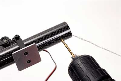
Insert the tail boom
into part 426 (body boom support block) Place the
belt around the gear. Pull the tail boom back
until the belt is tight. Use a sharp object and
mark the tail boom through the block of where you will
be drilling the hole for the screw. Make sure the
main body is leveled and the
tail's fin is 90° vertical when marking the hole.
Then remove the tail
boom and block. |
|
| |
|
|
 |
|
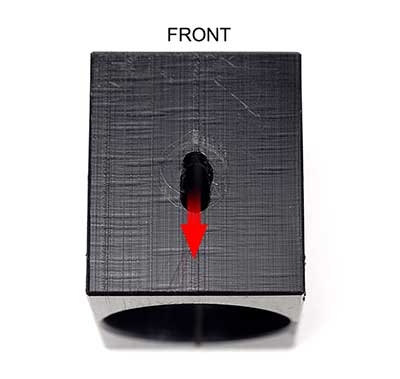
OPTIONAL:
To be able to tighten
the tail boom belt just a little more, just in
case you feel it's not tight enough, I lengthened the
hole towards the rear of the tail boom block. This
way just pull on the tail boom to tighten. The
screw and nut for the ground wire will just have to be
tight enough but not too tight. |
|
| |
|
|
 |
|
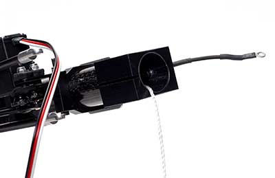
Tie a string to the
belt from the front end. Pull the belt from the
rear. |
|
| |
|
|
 |
|
| |
|
|
 |
|
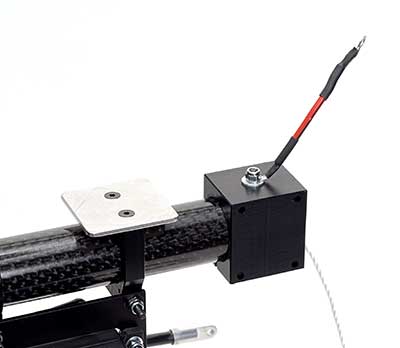
Insert the screw from
the inside. |
|
| |
|
|
 |
|
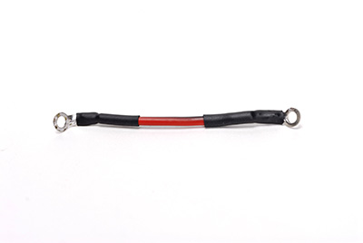
Put one end of the
ground wire first, washer then nut.
Pull the belt out
with the string. |
|
| |
|
|
 |
|
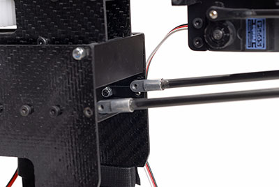
When sliding in the
tail boom keep in mind the supports. You can mount
them either from the outside or inside. |
|
| |
|
|
 |
|
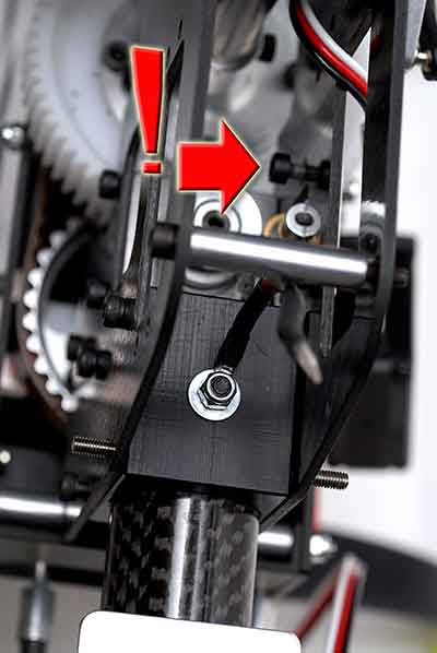
Mount the tail boom
with the support block. Make sure the belt
is tight.
Notice the
loose screw for part 472 that holds the tail belt
roller. Tighten this after. |
|
| |
|
|
 |
|
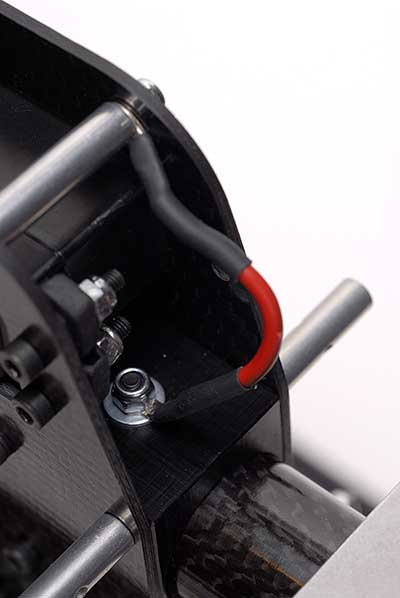
Secure the other end
of the ground wire as shown. |
|
| |
|
|
 |
|
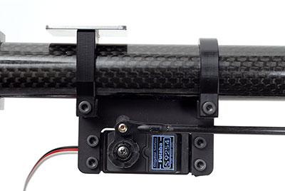
Adjust part 391 (gyro
plate mount) either forward or backward so that the servo horn
is vertical and the long end of the bellcrank on the
tail rotor is 90° perpendicular to the tail boom.
When you have this set, tighten the mount.
At this point the ball joint shouldn't have been glued
down yet. Use epoxy |
|
| |
|
|
 |
|
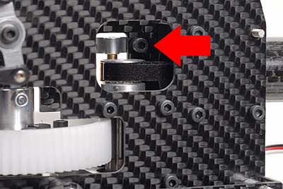
Don't forget to
tighten the screws for part 472 from drawing #7b.
This holds the tail belt roller.
NOTE: Read this
forum thread.
PINION (opens in new window) |
|
| |
|