|
 |
|
| |
|
|
 |
|
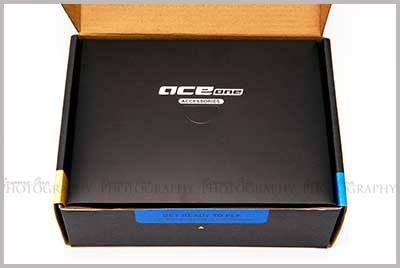
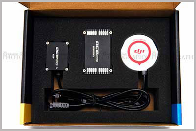
What you see first
upon opening. |
|
| |
|
|
 |
|
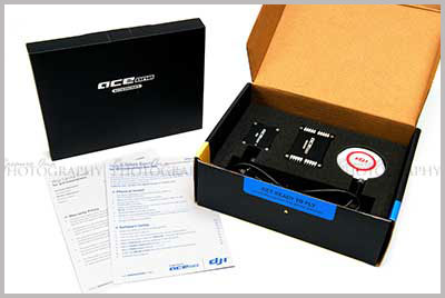
Warranty Information
card and Quick Start Guide that contains your serial
number. |
|
| |
|
|
 |
|
Modules are
adequately protected. |
|
|
|
|
|
 |
|
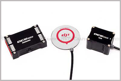
From left to right:
► Main controller
► GPS/Compass
► IMU |
|
|
|
|
|
 |
|
| |
|
|
 |
|
| |
|
|
 |
|
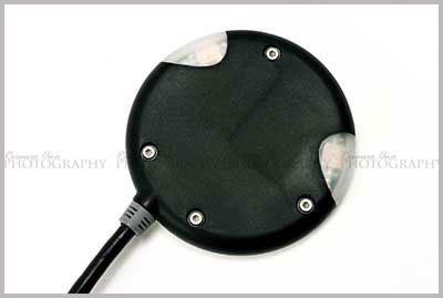
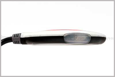
GPS/Compass side
profile. |
|
| |
|
|
 |
|
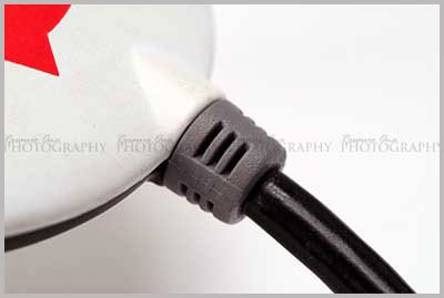
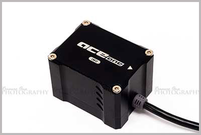
Both GPS and IMU have cable stress relief. |
|
| |
|
|
 |
|
| |
|
 |
|
| |
|
|
 \ \ |
|
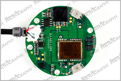
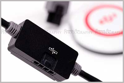
ACE ONE's modules use CAN-Bus connection. |
|
| |
|
 |
|
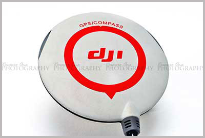
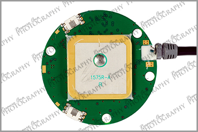
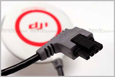
The GPS/Compass has
an in-line CAN-Bus connection port. |
|
| |
|
 |
|
| |
|
 |
|
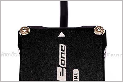
This arrow on the IMU
is important during the setup process. |
|
| |
|
 |
|
| |
|
 |
|
| |
|
 |
|
| |
|
 |
|
| |
|
 |
|
|
|
|
 |
|
| |
|
 |
|
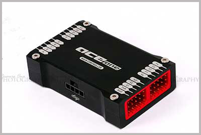
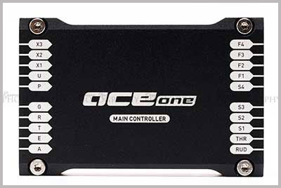
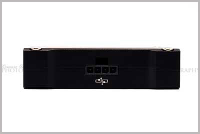
Main Controller
input/output servo ports.
Notice the Futaba
style ports. |
|
| |
|
 |
|
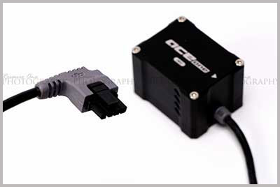
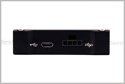
Main Controller's USB
and CAN-Bus port. |
|
| |
|
 |
|
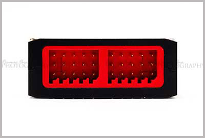
Main Controller has
another CAN-Bus port on the other side. |
|
| |
|
 |
|
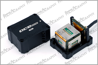
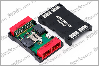
Inside the Main Controller |
|
| |
|
 |
|
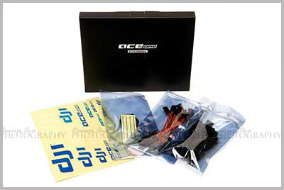
The contents of the
slim black box. |
|
| |
|
 |
|
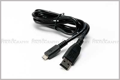
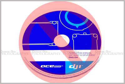
USB cable that is
used to connect the Main Controller to your computer. |
|
| |
|
 |
|
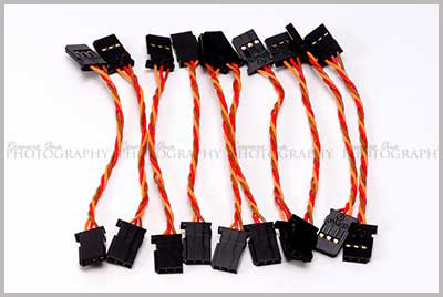
10 servo extension cables that
are used to connect the receiver to the input ports of
the Main Controller. |
|
| |
|
 |
|
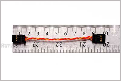
Servo cable is
approximately 10 cm. |
|
| |
|
 |
|
The GPS/Compass
tailboom mount and 3M 5925 double sided tape. |
|
| |
|
 |
|
| |
|
 |
|
| |
|