|
 |
|
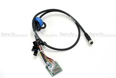
The RC Module
connects the Profi to the servos and receiver. |
|
| |
|
|
 |
|
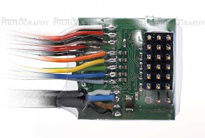
Carefully study the
pin assignment. |
|
| |
|
|
 |
|
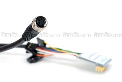
Note the connection's
orientation. |
|
| |
|
|
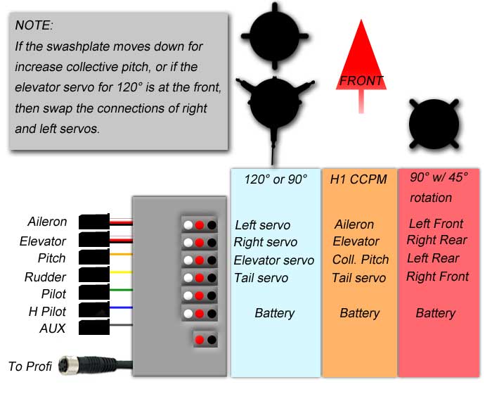
Follow the wiring
diagram below.
NOTE:
There is NO relation between the leads
(left side) and pins (right side). i.e. Many make
the mistake of of lining up the aileron lead on the left
to the first row of pins to the right.
|
|
|
|
 |
|
|
|
 |
|
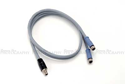
The regulator cable
connects the GPS, Profi and PC.
I installed this at
this point as it had to go inside my "blackbox". |
|
|
|
|
 |
|
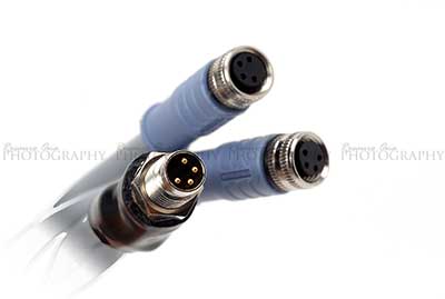
A closer look at the
connectors.
Note: One
"female" side is shorter than the other. They are
electronically identical and are interchangeable. |
|
|
|
|
|
 |
|
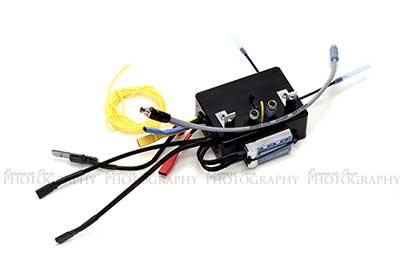
I made a "blackbox"
to easily connect all the components together.
The "blackbox"
contains the receiver and RC Module and cable slack.
Notice the color
coding for the servo wires.
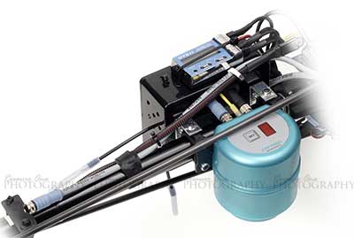
Shown on the outside
is Futaba 611 gyro control module installed on top.
This was temporary until the first test flight.
Later on I switched to the internal gyro.
|
|
| |
|
|
 |
|
The "blackbox"
installed. |
|
| |
|
|
 |
|
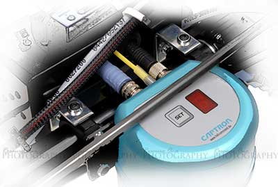
Note the screw holes
where tail boom brace would screw into are used for the
L-brackets on the blackbox.
Also notice the tail
boom brace on the right side has been repositioned above
the Profi to avoid blocking the optics. |
|
| |
|